|
Christmas Tree | |
 |
Here is a fun project to put on your Christmas Tree or in your front window to impress the neighbours. |
|
Christmas Tree | |
|
Here is a fun project to put on your Christmas Tree or in your front window to impress the neighbours. |
Multi-Coloured Christmas Tree
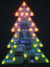
Looking for something different to build this Christmas? Try our Multi-Coloured Christmas Tree. It will look great at the top of your Christmas tree or in the front window.
In 1999 we published our Flashing Heart (Kit 136) and Christmas Star (Kit 46.) Now our "just for fun" project is in the shape of a tree but we have gone one step further by using bi-coloured LEDs. Also there are many different light patterns because we have used an EEPROM IC, and each LED can produce 16 different colours.
Yes, you guessed it. The Tree is controlled by a microcontroller but this one is different. While it can be programmed by most "high-end" (expensive) chip programmers, it can also be programmed (and re-programmed) by a PC parallel port with minimal hardware. This makes it ideal for hobbyists. If you have been avoiding microcontrollers because of the cost of the programming hardware, now there is no excuse! And most of the development software can be downloaded free from the Internet – there goes another excuse!
Circuit description
The key to understanding any circuit is "divide and conquer" - break it down into functional blocks. There are 3 main blocks in the Tree. The first, the power supply, is very straight forward. 9Vdc should be applied to SK1. Reverse polarity protection is provided by D1. U2 then regulates down to 5V for the LEDs and the logic. Bypass capacitors C4 and C5 ensure the 7805 remains stable.
Next is the microcontroller or MCU. In our two previous projects, we used the Atmel AT89C2051. However, the I/O port structure is not quite suitable for this application so we have used the similar Atmel AT90S2313. The main feature influencing this decision is that the ‘2313 outputs can be "turned off" while the ‘2051 outputs always have pullups enabled. When I said the ‘2313 is similar to the ‘2051, I was referring to the arrangement of I/O pins and their functions. Inside, the two chips are quite different. See the sidebar "What’s in the AT90S2313" for a description of the microcontroller.
U3 (24C16) is a serial EEPROM where the pattern data (treedata.hex) is stored. While the ‘2313 has some EEPROM on chip (128 bytes), this was not enough for the number of patterns we wanted to provide.
The final block is, of course, the LEDs. At first glance, the PCB looks like it contains 32 LEDs. In reality, there are 64 LEDs as each is a bi-colour LED capable of glowing red or green. Two pin bi-colour LEDs were chosen to reduce the number of PCB tracks and MCU pins required – the three pin LEDs would have been easier to drive and would have required more MCU pins.
As you may expect, the LEDs are multiplexed. To control so many LEDs with so few MCU pins, we connect the LEDs in a matrix of 4 columns with 8 LEDs in each and use 12 pins. Multiplexing is where each column of LEDs is activated for a short time followed by the next column. If each time slot is short enough, our eyes don’t see any flicker.
While there are only 4 columns on the schematic, we have to drive each column twice in each multiplex cycle (once in each polarity) so we can activate the red and green LEDs. Consequently, each LED’s timeslot is 1/8 of the total. This is a practical minimum duty-cycle as the brightness reduces.
Resistors R6 to R13 set the peak LED current to about 30mA. Because there can only be 8 LEDs on at any time, the total maximum current drawn by the Tree is about 400mA. Any 9Vdc plug pack rated at 500mA or more should be suitable. In practice, a 150mA 9V unregulated plug pack supply works with the 47R resistors as maximum current draw only occurs for "full brightness yellow" which does not occur very often.
Unfortunately, the microcontroller can’t drive the LEDs directly because maximum current ratings would be exceeded (risking loss of magic smoke!). So each pin is buffered by an emitter follower. Because each LED package has two LEDs connected in inverse parallel, the emitter followers have to be "bi-polar" so they can both source and sink current.
So, where a more conventional LED matrix would have 4 high current source drivers and 8 lower current sink drivers, this design has drivers that can source and sink.
Software
The software source code for the Tree is available for download from here.. The software was written in C and compiled by the Dunfield Micro/C compiler which is available from grantronics.com.au.
As each byte of pattern data is read in, it is processed by a simple interpreter. So each byte is an instruction such as "set colour to red" or "set Led 22 to the current colour" or "pause for 500ms". All the complex light patterns are built from these and similar simple instructions.
With all the technical stuff out of the way, lets get the soldering iron going and start building. Your soldering iron should be temperature controlled (about 600F, 320C) with a fine tip.
Visually check the PCB for shorts between tracks and broken tracks. As usual, start with the lowest items such as wire links and resistors. Next, fit the IC sockets, crystal, small capacitors, regulator and input diode. The regulator should be bolted to the PCB to provide some heatsinking.
The transistors should be fitted next. All the BC547’s face one way and all the BC557’s face the other way. Look at the overlay. There are 6 groups of 4 transistors. Now you can fit the LEDs. Be careful to insert them the right way and don’t apply too much heat as the leads are very short when the LED is pushed down against the board. Finally, C3 and the DC power connector should be fitted.
Testing
Carefully check your soldering – use a magnifying glass and a good light. Mistakes found now are less embarrassing than damaged components later! Don’t plug in the two DIL ICs yet.
Do a quick continuity check using your multimeter’s diode check range between U1 pin 10 (-) and every other pin of U1. There should be no shorts or diode junctions. Reverse the probes and you should see diodes (base-collector junctions) on the 12 pins that connect to the LED matrix. A similar test should be performed with U1 pin 20 (+) as the common pin. This may seem like a lot of work but a solder blob shorting a U1 I/O pin to 0V or +5 may damage U1 and spoil your Christmas!
When you are satisfied with your workmanship, connect 9Vdc. No LEDs should light. Measure U1 pin 10 (-) to pin 20 (+). You should have 4.8V to 5.2V. If all is well, remove power and plug in U1 and U3. Make sure they are correctly oriented and be careful not to bend any pins as you plug them into the sockets.
Turn your Tree on and the display sequence should start within a few seconds.
If it doesn’t work…
Modern electronic components are very reliable and faulty new components are very rare. The reality is that the most common causes of problems are soldering, wrong component or wrong component orientation. So the first step in sorting out problems is to thoroughly check your workmanship (or should that be workpersonship…?).
After that, we need to get more logical. If a few LEDs don’t work, are they all in a single column or row? Maybe they only glow red and not green? The column drivers go high and the rows go low for red and vice versa for green. To help with fault finding, the first few patterns are simple "all one colour" displays. The patterns get more interesting after that…
I hope you have as much fun building and watching the Christmas Tree as we did designing it.
We hope you have as much fun building the Tree and playing with the software as we did creating it. Enjoy!
Modifications
If you must run the Tree from a 12V supply, mount the regulator on the back of the PCB (plastic body to PCB, bend the legs up instead of down) with a small heatsink. You will need a longer screw with a couple of nuts as a spacer.
| Parts List | |
| Quantity | Description |
| Hardware | |
| 1 | PC board type TREE |
| 1 | "DC" connector, 2.5mm (SK1) |
| 1 | 4.00MHz crystal (X1) |
| 1 | 8 pin IC socket |
| 1 | 20 pin IC socket |
| 1 | 3 x 8mm screw and nut |
| Semiconductors | |
| 1 | AT90S2313 (programmed) (U1) |
| 1 | 7805 (or LM340T-5) regulator (U2) |
| 1 | 24C16 EEPROM (programmed) (U3) |
| 32 | Bi-Colour LEDs |
| 12 | BC547 or similar NPN transistor (Q1-Q23, odd numbers) |
| 12 | BC557 or similar PNP transistor (Q2-Q24, even numbers) |
| 1 | 1N4004 power diode (D1) |
| 1 | 1N4148 diode (D2) |
| Resistors (0.25W, 5% tolerance) | |
| 8 | 47R or 100R (R6-R13) |
| Capacitors | |
| 2 | 27pF or 33pF ceramic (C1-C2) |
| 3 | 100n monolithic (C4-C6) |
| 1 | 1uF 16VW+ RB electrolytic (C3) |
What’s in the AT90S2313?
The AT90S2313 is a member of the Atmel AVR family of microcontrollers that range from tiny 8 pin packages to a 64 pin feature-packed "monster". Here is a short summary of the features of the ‘2313:
Download the Tree
software source code from our software download page. (12k ZIP).
Download the Tree schematic from our kits.html page
(29k PDF).
To compile the software, you will need a C compiler such as Dunfield Micro/C from www.grantronics.com.au