Christmas Star |
|
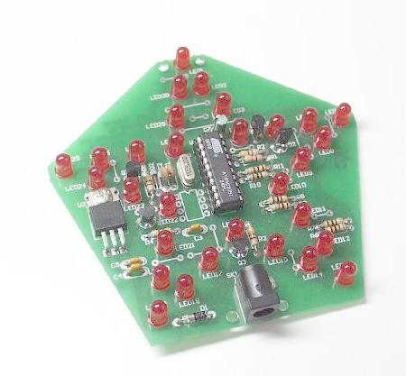 |
Here is a fun project that can add that
"something different" to your Christmas tree. Or put it in the front window to impress the neighbours! |
| Kit 46. Christmas Star |
The Christmas Star project
was published in the November 1998 issue of Silicon Chip magazine.
A summary of that article appears below.
Christmas Star |
|
|
Here is a fun project that can add that
"something different" to your Christmas tree. Or put it in the front window to impress the neighbours! |
Why use a Microcontroller?
Using a PC parallel port to control external devices is a popular approach these days but I certainly couldn’t afford to tie up a PC for the few weeks leading up to Christmas just to flash a few LEDs! Not to mention the power bill! So, why not use a small microcontroller? They are cheap and easy to use and if the design doesn’t work first time (when does it?), you simple re-program it.
Also, you can easily create something using a micro that is the equivalent of many discrete logic chips. In this case, the circuit is simple enough to lash up on VeroBoard™ though it is much easier to use a printed circuit board. To do the star in discrete logic would be a nightmare!
Given a few inexpensive software tools, a microcontroller such as the Atmel AT89C2051 should be just as easy to use as a handful of 4000-series CMOS chips. In my experience, the micro is usually easier!
Another reason for using a micro is that micros are the future of electronics. While it is useful to know how to design with 4000-series logic, most new products require more than can be easily done in discrete logic. I believe there is actually a commercially available toaster that uses a micro! While some would say that this is an extreme example, it does indicate how far micros have entered our lives.
So what’s in a ‘2051?
The Atmel AT89C2051 is a relatively recent derivative of the venerable 8051. It comes in a diminutive 20 pin skinny-DIP plastic package and contains 2k bytes of program memory, 128 bytes of RAM, 15 programmable I/O lines, on-chip oscillator, two 16 bit counter/timers, six interrupt sources and a full duplex serial port (UART). This all sounds very much like a small 8051 until we add that the program memory is re-programmable Flash with 1000 erase/write cycles, the oscillator runs to 24MHz (double that of the original 8051), the I/O pins can sink 20mA for directly driving LEDs and two I/O pins are connected to an on-chip analogue comparator!
The Hardware
The heart of the hardware is, of course, the Atmel ‘2051 micro. To make it start thinking, we need a reset circuit consisting of C7. D2 forces C7 to discharge quickly when power is removed. To set how fast it thinks, we need an external crystal X1 and associated capacitors C1 and C2. Note that the crystal could be replaced by a 12MHz ceramic resonator. This allows the ‘2051 to execute an instruction every 1 or 2us.
As you can see from the schematic, the 30 LEDs are connected in an X-Y matrix. Why 30 LEDs? Engineering is full of trade-offs or compromises. I wanted a 5 pointed star so the number had to be divisible by 5. For aesthetic reasons, we need an even number of LEDs per point. Six LEDs per point looked "about right". The next step up would have been 40 LEDs which would have required 13 I/O pins to drive them and a more complicated PCB.
We can drive 30 LEDs from only 11 I/O pins using a process called multiplexing. The appropriate combination of LEDs in a column is switched on for a short time (about 2ms in this case). This process is repeated for each column in turn taking 10ms for a full cycle. Provided the multiplexing is done quickly enough, the persistence of the human eye "fills in the gaps" and we see any combination of LEDs on without any flicker. The minimum practical multiplexing frequency is about 100Hz which is the frequency used by the star.
The power supply uses the ubiquitous 7805 three terminal regulator with bypass capacitors C4 and C5. Diode D1 provides reverse polarity protection. The maximum current drawn by the star is about 150mA with all LEDs on but less than about 50mA for most patterns. The maximum temperature rise of the 7805 when the star is run from a typical 9Vdc unregulated plug-pack is about 30 degrees which is quite acceptable. It gets warmer when run from a 12Vdc unregulated plug-pack and should be provided with a small heatsink.
The Software
In the spirit of Christmas, we are making the basic source code available for free! An extended version that uses the EEPROM for storage is available at minimal cost. The software was written in the C language using the low cost Dunfield Development Systems Micro/C compiler. There is nothing particularly "smart" or "tricky" about the software – it was written to be easy to understand and to encourage use of small micros. Consequently, there are no interrupt routines and no use of the counter/timers, the UART or the comparator though Micro/C can make use of these resources.
The software is table driven. This means that the display patterns and sequences are determined by data stored in a table (an array of bytes). There is a simple interpreter that scans through the table to perform the specified operations. The defined byte values are listed in the following table.
| Byte value or range | Operation |
| 01 to 30 (0x01 to 0x1e) | Turn on LED 1 to 30 |
| 33 to 62 (0x21 to 0x3e) | Turn off LED 1 to 30 (LED number = byte – 32) |
| 64 (0x40) | Go back to byte after loop start |
| 65 to 79 (0x41 to 0x4f) | Loop start, count = byte – 64 |
| 128 (0x80) | Delay (use last delay count), each count = 10ms |
| 129 to 191 (0x81 to 0xbf) | Delay, count = byte – 128, each count = 10ms |
| 253 (0xfd) | All LEDs on |
| 254 (0xfe) | All LEDs off |
| 255 (0xff) | End of table |
Note that there are quite a few undefined values so future expansion is possible.
Putting it all together
Assembly is quite straight forward. You will need a soldering iron with a fine tip, preferable temperature controlled to about 600oF or 320oC. Carefully check for shorts between tracks and broken tracks. Fit the lowest parts first – the wire links and resistors and diodes. Next, fit the crystal (or resonator) and the IC sockets for the micro and EEPROM. Fit the transistors, capacitors and LEDs. Pay particular attention to the orientation of the LEDs – they don’t work when installed backwards! Finally, install the regulator and power socket.
Do another close visual inspection looking for solder bridges especially on the transistor pads.
Connect power and check for 5Vdc (4.8V to 5.2V) from U1 pin 20 (+) to U1 pin 10 (-). If all is OK, remove power, plug in the micro and turn it on.
The two holes near LED1 may be used to hang the star and the holes near SK1 may be used to secure the plug pack cable.
Finally, the appearance of the star may be enhanced by placing a piece of red cellophane over the front.
Fault finding
5Vdc not present: Check the applied power polarity – the centre pin of SK1 must be positive. Check that D1 is correctly fitted. Check tracks from SK1 via D1, the 7805 to U1 for breaks or shorts.
One LED does not work: It may be inserted backwards or it may be shorted.
One group of adjacent LEDs does not work: Check circuitry and soldering around the appropriate column drive transistor.
Several individual LEDs do not work: Check the corresponding row drive circuitry.
Remember, faulty components are rare, soldering problems are more common!
Parts List |
|
| Quantity | Description |
| Hardware | |
| 1 | PC board type STAR1SS |
| 1 | 2.5mm DC power jack connector (SK1) |
| 1 | 11 - 12MHz crystal (X1) |
| 1 | 8 pin IC socket (optional) |
| 1 | 20 pin IC socket |
| Semiconductors | |
| 1 | AT89C2051 (programmed) (U1) |
| 1 | 7805 regulator (U2) |
| 1 | 24C16 EEPROM (U12) (optional, enhanced version only) |
| 30 | Super bright red LEDs (LED1-LED30) |
| 5 | BC557, BC558 or similar PNP transistor (Q1-Q5) |
| 1 | 1N4004 power diode (D1) |
| 1 | 1N4148 diode (D2) |
| Resistors (0.25W, 5% tolerance) | |
| 5 | 470R (R1-R5) |
| 6 | 120R (R6-R11) |
| Capacitors | |
| 2 | 27p ceramic (C1-C2) |
| 3 | 100n monolithic (C3-C5) |
| 1 | 10uF or 2.2uF electrolytic (C7) |
Download the Christmas Star software
source code.
Download the Christmas Star
schematic